K3ZXL - 160 Meter Receiving Loop Project
Dan Schaaf
20 January 2010
_______________________________________________________
For several years, I have been struggling with atmospheric noise on the
160 meter band. I have no space on my city lot for a K9AY Loop or a
Beverage antenna. On one of the reflectors I saw a comment by N7TK, John,
that he uses a coaxial loop on 160 for receive. I asked him about his
success and his response was favorable enough to try one myself. I have
read in various books including the ARRL Antenna Book and ON4UN Low Band
DXing book that these loops are primarily used for manmade noise
rejection. But they are at the bottom of the ladder compared to Beverage
and AY Loops in performance. Nonetheless, I thought that I would try one.
I hopped into the car and went to the local Comcast center to see if I
could get a donation of hardline coax scraps. It was my lucky day, they
were taking down a 100 ft tower that was loaded with coax. I got about 100
feet in 20 and 40 ft pieces. They even delivered it to my home for $25
donation to the beer fund. The following pictures and text show how I
built it. I am extremely pleased in it's performance. No longer are my
ears burning with high levels of noise when trying to pick out a signal.
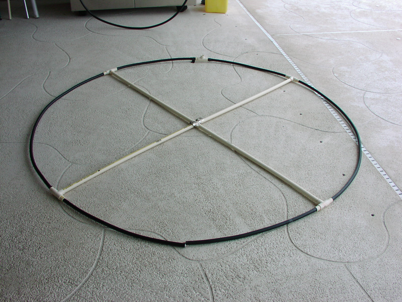
I decided that a 6 ft diameter loop would work out in terms of available
space. That calculates out to 6 x Pi = 19 ft of coax. I measured the
halfway point and cut out 1 inch of the aluminum shield using a copper
pipe cutter. Then with the help of my wife, and using the patio table as a
form, we bent it into a circle. I used 3/4 inch CPVC tubing to make the
crossmembers and support at the top of the loop to keep the loop from
kinking after the shield was removed since it is now a weak point in the
coax.
Here you can see the cut in the shield and the T fitting ready to
slide into place.As I said, I used a pipe cutter to break the shield then
I used a Dremel tool with a saw blade bit to slice the shield lengthwise
so that I could separate it and remove it.
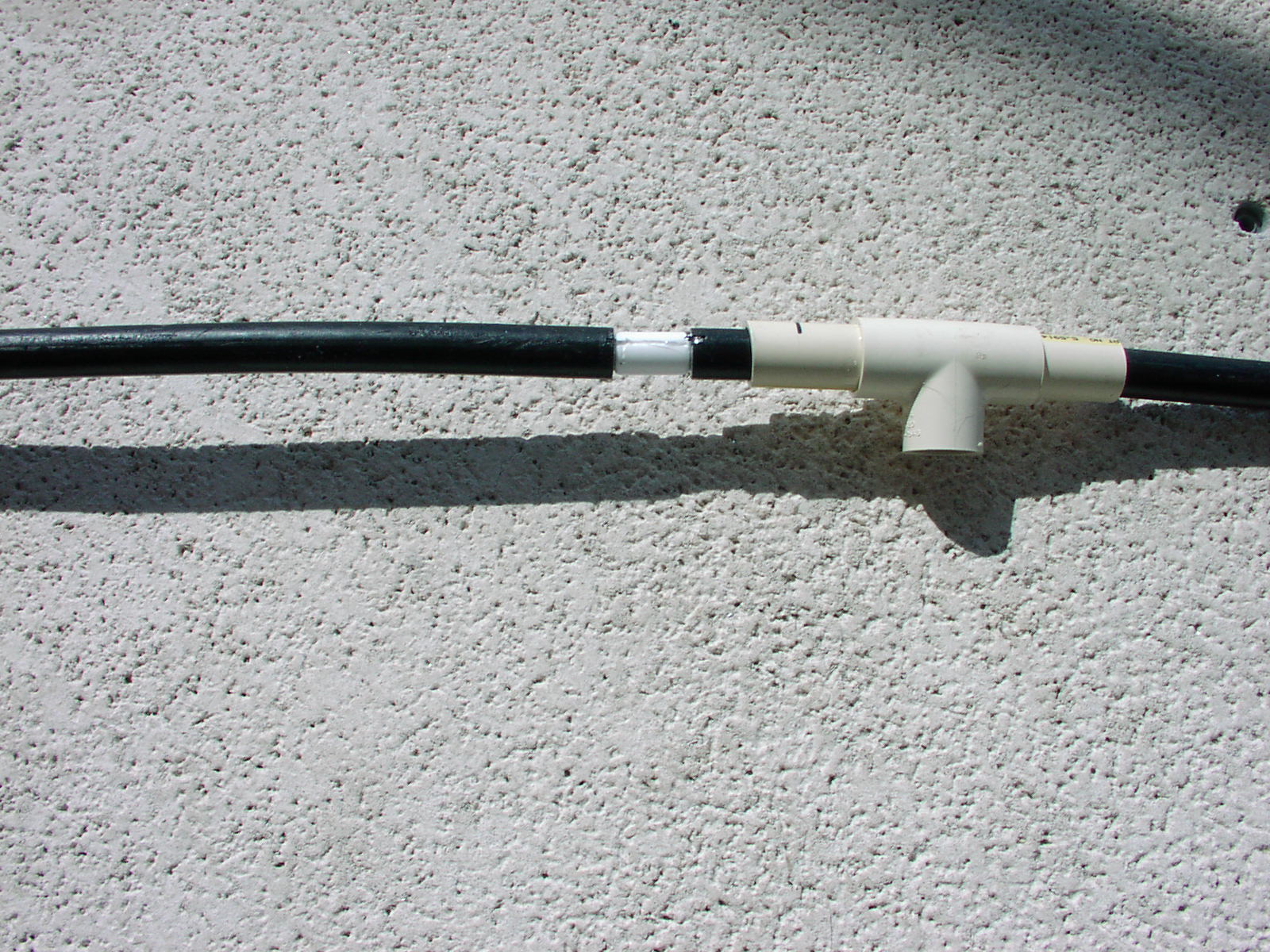
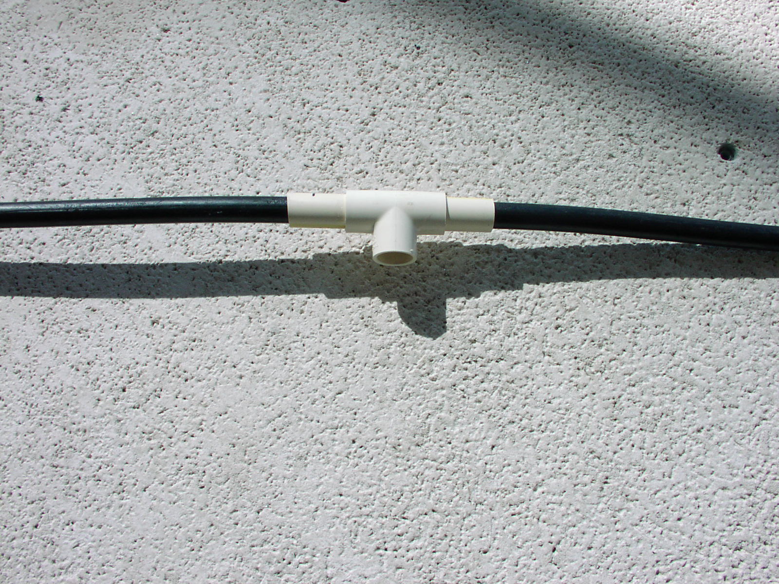
Here is the T fitting slid over the coax shield break.
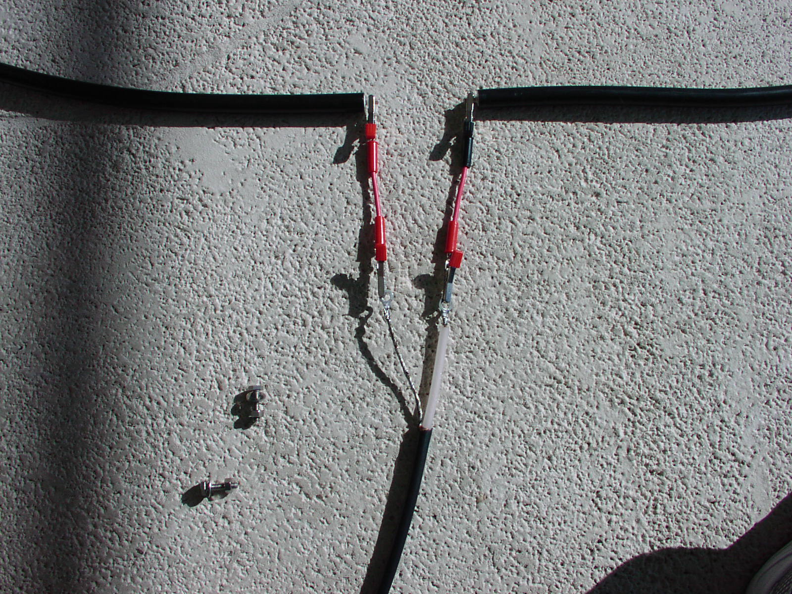
Next step was to bare the center conductor at the bottom of the loop
and make measurements with my MFJ-259B SWR Antenna analyzer. It is
necessary to measure the SWR, XL, XC, R, C and L at the frequency that you
want to center the SWR Bandwidth on. Keep the coax from the MFJ to the
clip leads as short as possible .
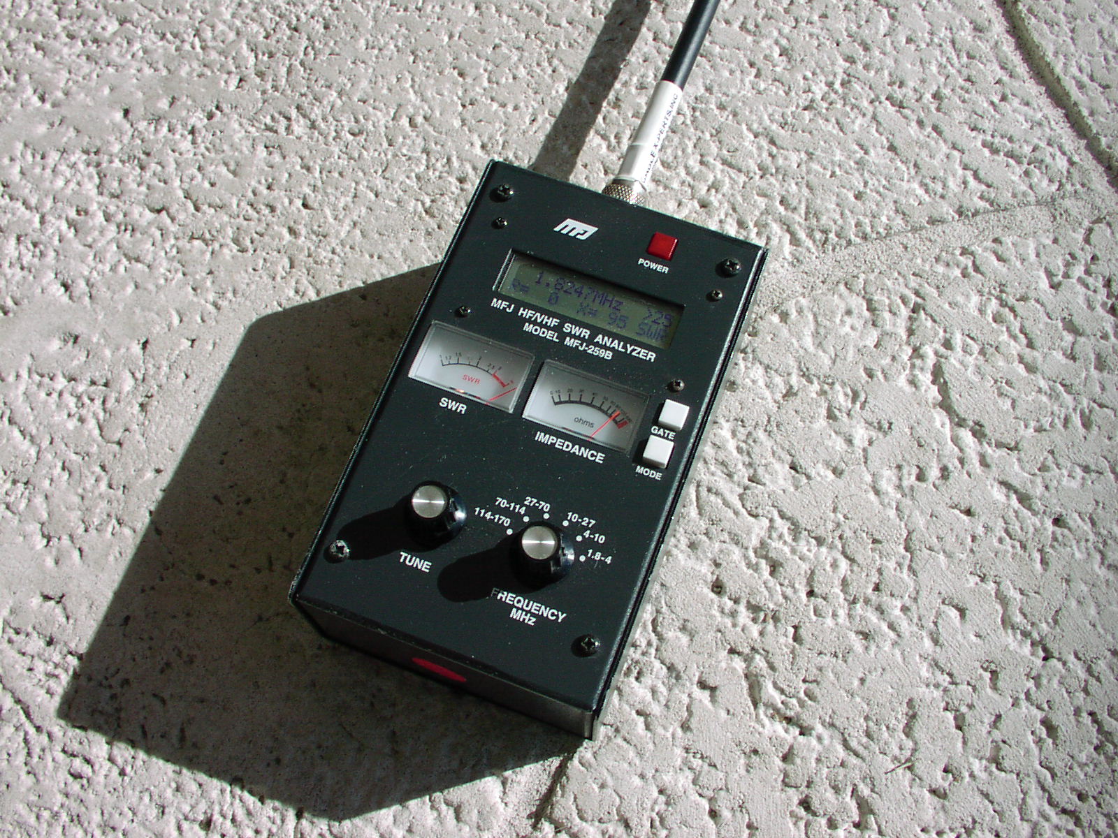
MFJ Analyzer making measurements
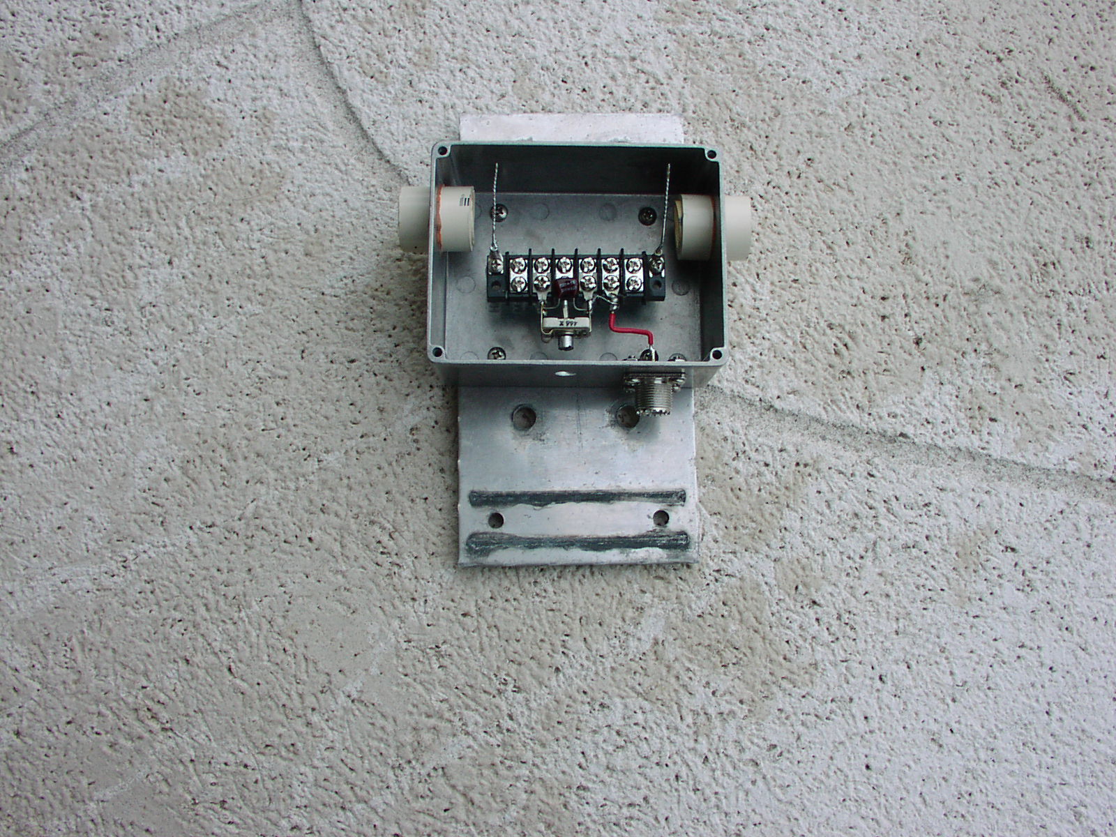
Loop Box prepared for hardline cable. I attached an aluminum box
purchased from DigiKey Corp. Drilled holes in the sides for the hardline
and then I took 3/4 inch CPVC tubing and secured it by taking CPVC
couplers and cutting 3/4 inch off each side of the coupler. These pieces
are glued together to keep the CPVC tubing from sliding in/out of the box.
This assembly prevents chafing of the coax jacket and makes a nice snug
fit for the coax. The terminal strip istands on standoffs to align the
coax and provides a convenient mount for the trimmer capacitor. The box is
grounded to the coax shields through the standoffs and the wires shown
which will connect to the coax shield.
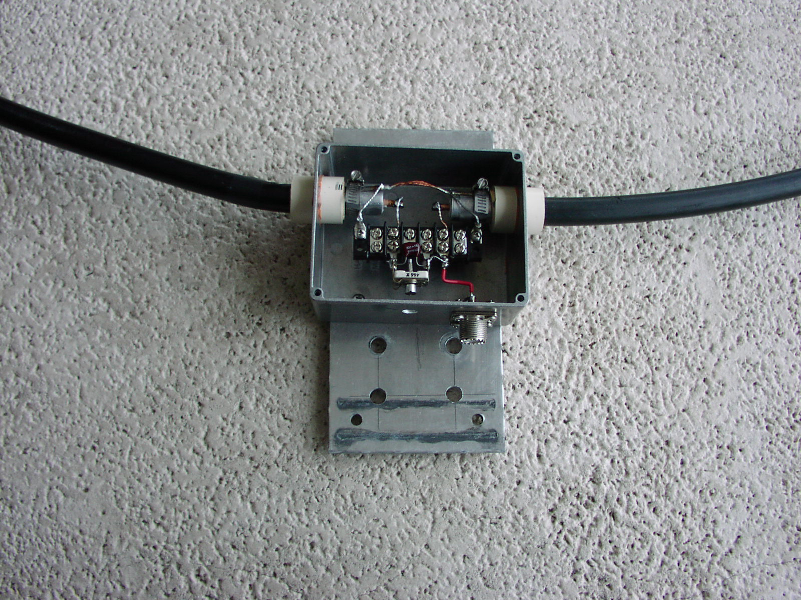
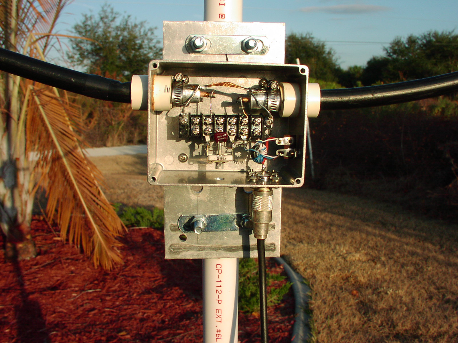
Here is the Loop box with all connections made. I used a piece of
RG-58 Braid to join the two ends of the hardline shield. They are hose
clamped onto the hardline. You cannot solder to aluminum shield. The hose
clamps also keep the coax from trying to slide out of the box. The trimmer
capacitor is connected through the terminal strip by wires to the center
conductor of the hardline.
Now the MFJ Analyzer is connected by a 6 inch piece of coax and the
trimmer is adjusted for low SWR at the frequency of interest, in my case
it is 1.825 MHz. Initially, I made the final measurement with the loop
laying on concrete, but when I mounted the loop in it's permanent place,
the tuning was way off. The concrete has a big influence on the tuning.
So, it is best to mount the antenna first then adjust the trimmer.
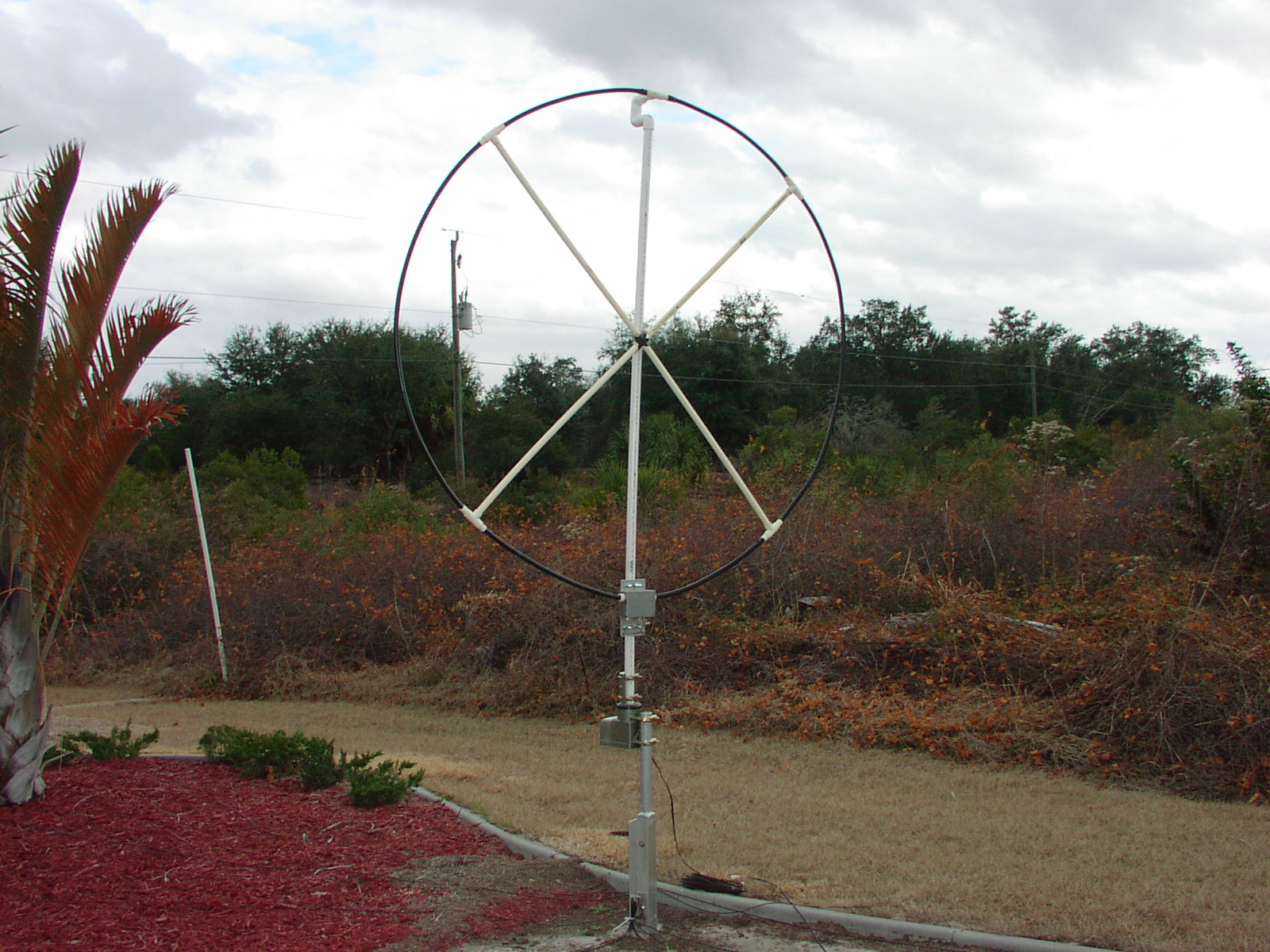
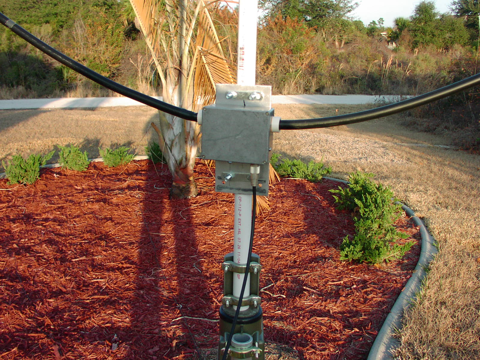
Here is the loop mounted on a TV rotator 3 ft above the ground. I
used another piece of PVC, 1 inch, to support the loop at the top and into
the rotator. Then used electrical tape to join all PVC at the center cross
point.
At nite and in the mornings I tested it on the air. The atmospheric
noise was just at the radio inherent noise level. The Feedpoint impedance
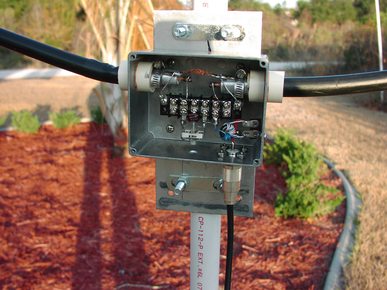
was measured at 16 ohms. At the suggestion of W8WWV, Greg, I installed a
torroid transformer with 5:9 turns ratio. The atmospheric noise rose above
the radio noise. Now the feedpoint impedance measures at 36 ohms. I could
probably change the turns ratio slightly to bring it to 50 ohms but I will
maybe do that later.
Here are pictures with the transformer installed.
Results:
When the noise on my vertical antenna is S9, the noise on the Loop is
S0 ( as long as there are no lightning storms that produce static crashes.
When signals are coming in at S9 on the vertical and the noise is S9 on
the vertical, the signals are S7 or S6 on the loop but the noise is S0 to
S1. Very comfortable listening. I have easily copied Russia, Ukraine, most
of EU, all of NA and Carribean if the propagation was acceptable to good.
I have not had good propagation to the Pacific in the last few days so no
comment as yet. This was assembled 2 days ago and today is January 19,
2010.
Note: Today is 20 January 2010.
I tweaked it !!! Removed one turn from the low Z side of the
transformer. Now it is 4:9 ratio instead of 5:9 , R increased from 36 to
51 ohms.
R = 51 ohms
XL = XC = 9 ohms
SWR = 1.2
F = 1.825 MHz
I will leave it alone. Worked Cyprus last nite for a new one. The
loop removes the noise. Signal strength seems 2 S units less than the
vertical on stronger signals. I have yet to get a read on a weak sig. Will
keep looking for one. It was suggested by a friend of mine that the rebar
in the concrete floor probably detuned it when I was in the initial stages
of testing and construction. I am sure he was correct.
23 January 2011: My Birthday.
Worked VQ9LA ( 10,232 miles ) hearing with this loop. Propagation was very
very favorable for me. Have also worked VK6HD ( also 10,232 miles )
hearing with this loop. Again, good propagation.
Don't get me wrong, the signals are typically quite low on these loops
but still workable. I find that if I can hear them I can work them becuase
I consistently get good reports from the DX stations like 559 or 579.
Caveat: This antenna is not as
sensitive as a Beverage or DX Engineering 8 circle array or HiZ 8 circle
array, but it does pretty well. Whatever I hear on my K9AY Loop, I also
hear on this coax loop. Many times the Signal to Noise is better on this
coax loop than the K9AY Loop. I have an A/B switch in the shack so that I
can switch between the 2 loop antennas. I also have a Clifton Labs 20 db
preamp in the shack, but rarely need it since the loops put out sufficient
signal and noise that I do not need any further amplification beyond what
my FT-2000 provides.
18 December 2011 :
Yesterday, I heard XU7ACY weak in the noise, but that was very
encouraging. To date, I have worked most DXPeditions listening with this
loop.
Found that the loop resonant point would drift with either humidity
changes or with temperature changes. I think that the trimmer capacitor is
affected the most by either humidity or temperature. Today, I installed
fixed capacitors ( mica ) to replace the combination of trimmer and fixed
capacitors. I had to make a network of parallel and series capacitors to
get resonance at 1.825 MHz. It took 921 pf total. I will now watch over
the days ahead for any drift in resonant frequency.
29 December 2011 :
Today, I heard XU7ACY weak in the noise again, but that was more
encouraging. I worked VK3ZL over 10,000 miles. Very Very Strong Same level
on both this coax loop and the K9AY Loop.
30 December 2011 :
Worked VK3IO today 10,200 miles. Very Strong here. More exciting was
that while I was tuning the VFO I heard a pileup. I tuned down 1 KHz and
there was a DX station giving reports. So, I called up 1 from him and he
came back on my first call. It was XU7ACY. !!!!! SWEET, 9,500 miles .This
gave me 144 countries on 160 and a new CQ Zone for 34 Zones now on 160.
For the past 2 days propagation has been very excellent to the S. Pacific.
Using my Clifton labs 20 db preamp in the shack + the FT-2000 IPO and APF
CW Filter, XU7ACY was S4 on the meter. Other hams in the USA were hearing
him S9 on their Beverages and on their 8 Element arrays. This tells me
that both loops are 5 S units lower than the high performance RX antennas
which is approximately 30 db lower.
OK, so I have to be patient and wait for propagation to be really
strong to work some of these long distance countries. But it can be done.
Hopefully this propagation will continue for some days and maybe I can
also log one of the DU1 stations.
BTW, these stations are giving me 579 to 589 reports, so my low band
vertical is doing it's job on transmit.
http://k3zxl.com/Tower_Vertical/ZXL-Super%20Vertical.htm
Box Closed.
The Schematic of the loop is as shown. The value of the capacitor was
chosen for the 80 meter band. My capacitor is in the 900 pf range. Here is
the link to Greg's page on his 80 meter loop antenna.
http://seed-solutions.com/gregordy/Amateur%20Radio/Experimentation/3805er.htm
If you have any questions, feel free to contact me by email. I am good on
www.QRZ.com